| Systems Analysis and Optimization
Overview of Operational Safety Concepts for Level 4 Automated Driving System Fleets
Project Description
The topic addresses safety risks associated with ongoing Automated Driving System (ADS) fleet operations used in Mobility as a Service (MaaS) applications. Mobility as a Service (MaaS) integrates various forms of transport and transport-related services into a single, comprehensive, and on-demand mobility service. Within the transport environment, the main role of the Fleet Operator is to ensure the correct and safe operation of the fleet based on the technical requirements of the ADS manufacturer and comply with additional MaaS operational requirements.
This article describes different methodologies to derive responsibilities and activities (i.e. policies, procedures, and strategies) of the fleet operator to mitigate operational safety risks, as well as identifying relevant operational safety best practices being applied by commercial vehicle fleets (light and heavy duty), ADS developers who are beginning to operate ADS fleets; and potentially, other transportation modes such as aviation, rail, and buses.
Safety Concepts for Level 4 ADS Fleets: Deriving Risk Mitigation Activities for Fleet Operators
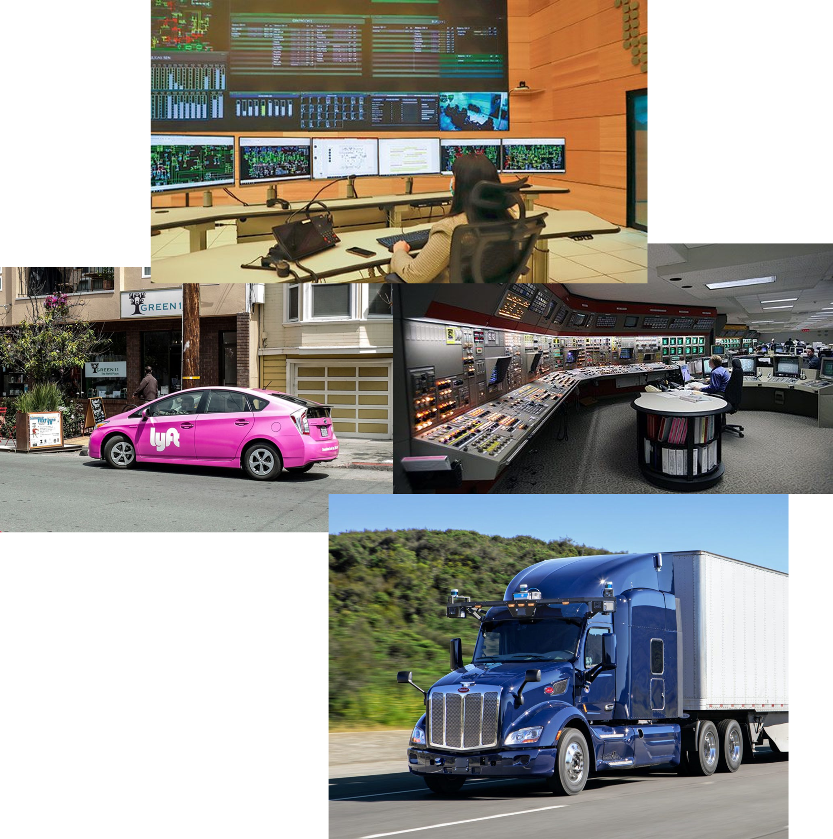
Many companies are currently developing, testing and operating different fleet models for Mobility as a Service (MaaS). Aiming to develop common risk mitigation activities for Fleet Operators, we define a generic Level 4 ADS fleet based on publicly available information and discussions with relevant stakeholders. Our generic fleet is defined by:
- An expected 24/7 ride-hailing service in urban areas with multiple storage depots.
- The vehicle fleet is owned by a Fleet Operator who has acquired the vehicles from an ADS Developer. The vehicles may be electric or hybrid light-duty passenger vehicle and SUVs sourced from multiple vehicle OEMs.
- Riders book rides via a mobile app. They get visual and audio updates on vehicle status (like battery level and trip details) and have access to emergency stop and support features.
- The vehicle performs L4 ADS capabilities using real-time single-vehicle perception, planning, and control functions. The ADS can achieve a Minimal Risk Condition (MRC) with no human intervention when triggered by self-diagnostic system.
- The fleet operates within an Operational Design Domain (ODD) with restrictions based on geofencing and environmental conditions.
- A Fleet Operations Center (FOC) supports the passenger transport service by continuously monitoring the fleet, providing passenger support, and overseeing post-crash procedures.
- Periodic inspection and maintenance operations are coordinated by a Maintenance Operations Center (MOC) to maintain the operation of the fleet as intended by the ADS Developer.
- The Fleet Operator regularly engages with the ADS Developer to address gaps in operational experience, edge cases and incident reviews, as well as coordinating remote operator and maintenance crew training programs.
Assessing Safety & Risk: Hazard Identification
Hazard identification and modeling are key to conducting qualitative and quantitative risk assessments. Traditionally, industries and researchers have used several methods to understand and mitigate risks. These include: fault tree analysis (FTA), event trees analysis (ETA), event sequence diagrams (ESDs), failure mode and effect analysis (FMEA), hazard and operability studies (HAZOP), and, more recently, Bayesian networks (BNs).
These tools help identify and model hazards in systems, typically focusing on issues arising from hardware or software malfunctions, and providing a sound basis for risk quantification. While these methods improve design reliability, complex systems involve more intricate interactions and feedback loops, which can lead to new, emergent behaviors. To address this, newer methods like Concurrent Task Analysis (CoTA) and System-Theoretic Process Analysis (STPA) have been introduced.
Our hazard identification methodology combines traditional tools with newer approaches to handle the complexities of ADS vehicles and human systems. The process involves three phases (Figure 1):
- System Modeling: Creating a detailed model of the system.
- Scenario Modeling: Developing scenarios that the system may encounter.
- Hazard Identification: Identifying potential hazards using various tools.
This integrated approach helps us better understand and manage the risks associated with advanced systems, helping us answer the following questions:
- What went wrong? (a)
- Who contributed to it? (b)
- How did it happen? (c)
- Why did it happen? (d)
- What are the consequences? (e)
Click here to learn more about the hazard identification methodology.
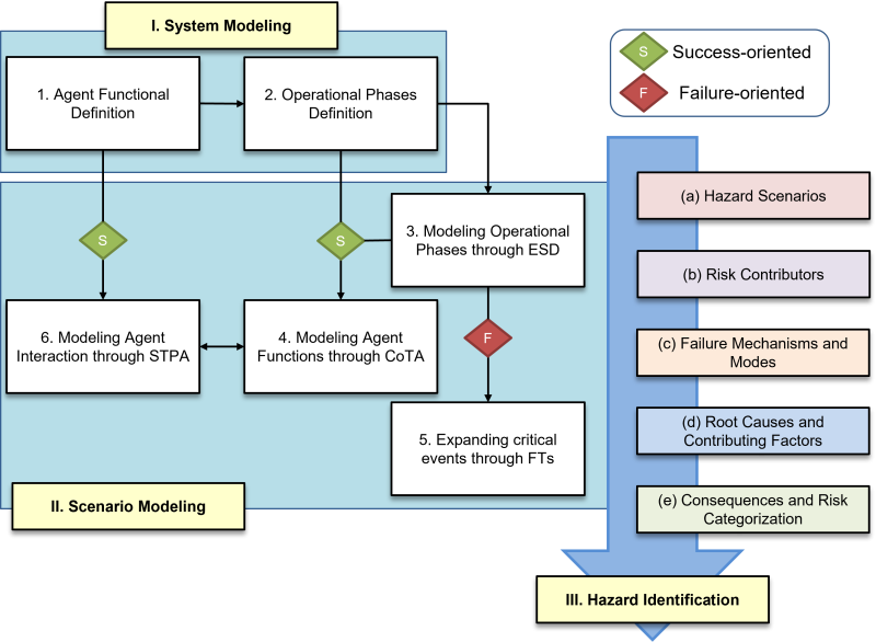
Figure 1: Overview of Hazard Identification Methodology.
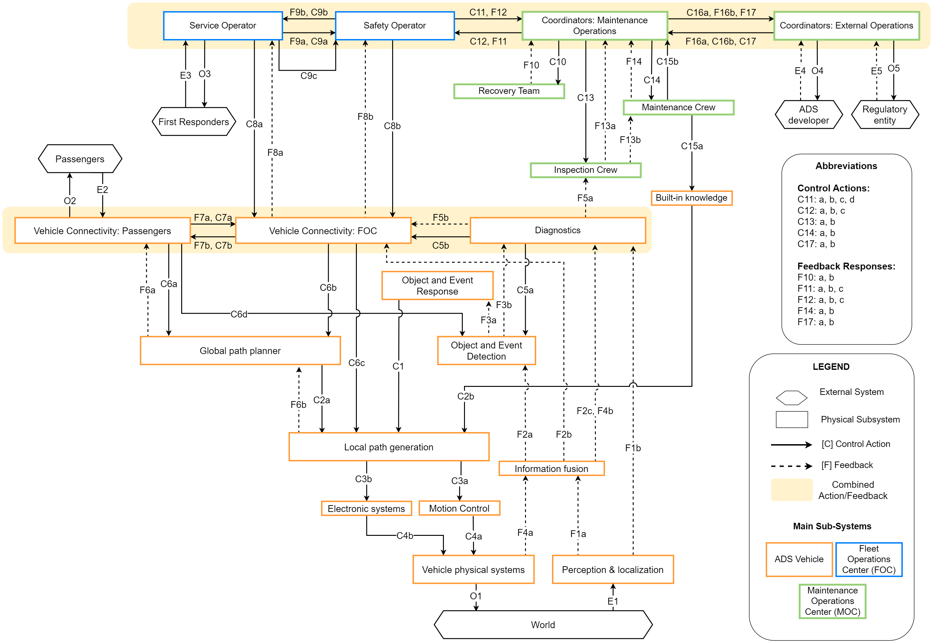
1. System Modeling: Understanding Roles and Functions
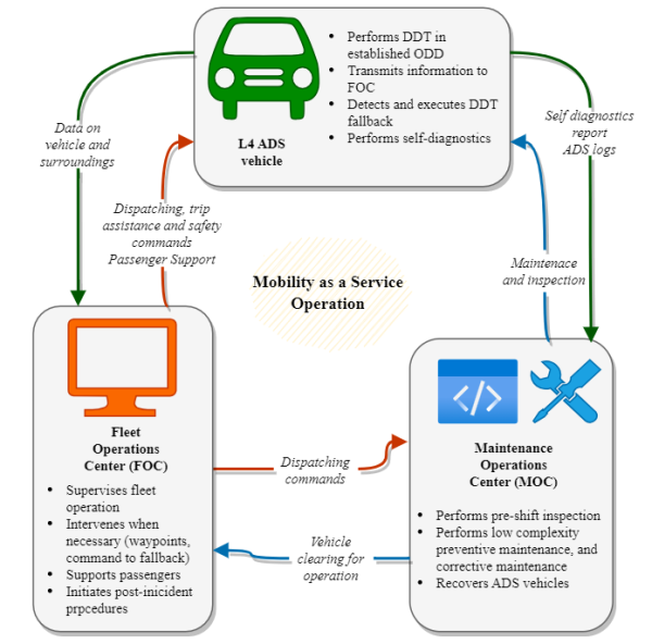
Figure 2: Simplified diagram of agents’ functional breakdown.
The generic fleet operation is defined in further detail as shown in Figure 2: The ADS vehicle performs the driving tasks, passenger pick-up and drop-off. The Fleet Operations Center (FOC) monitors and supervises the ADS vehicle’s operation, while the Maintenance Operations Center (MOC) inspects, maintains, and stores the vehicles.
The ADS vehicle performs automated driving tasks in line with Level 4 ADS expectations. Its role is to transport passengers while managing Dynamic Driving Tasks (DDTs) within a specified Operational Design Domain (ODD). If any issues arise, the ADS will execute fallback strategies to reach a Stable Stopped Condition (SSC) or a Minimal Risk Condition (MRC), either determined by the ADS or commanded by the Fleet Operations Center (FOC).
The main ADS vehicle functions are:
- Mobility as a Service (MaaS):
- Picking up and dropping off passengers
- Facilitating communication between the vehicle and the remote operators at the FOC
- Entering SSC if a passenger requests an emergency stop
- Automated Driving:
- Managing hardware and software for vehicle perception, planning, and control
- Ensuring correct Object and Event Detection and Response (OEDR) functionality
- Determining and executing DDT fallback strategies
- Continuously monitoring the vehicle’s status with a diagnostics module
The Fleet Operations Center (FOC) is a physical space staffed by trained Remote Operators who oversee the fleet operation. In case of accidents, the FOC initiates post-incident procedures, contacts first responders, and sends recovery teams to the accident site. Direct remote control (“remote driving”) is not considered. Remote operators are limited to providing “remote assistance”, such as providing trajectory waypoints or guiding vehicles to achieve MRC to ensure safety while awaiting post-incident procedures. In addition, some operators may focus exclusively on performing customer and service assistance functions.
The main Remote Operator’s functions are:
- Supervision:
- Overseeing ADS vehicle operations and monitoring vehicle and passenger status.
- Assisting OEDR functions when alerted by the ADS vehicle.
- Directing DDT fallback strategies, such as guiding vehicles through difficult situations and triggering MRC remotely if needed.
- Reporting:
- Reporting unusual vehicle behavior to the Maintenance Operations Center (MOC).
- Contacting law enforcement and first responders in case of incidents.
- Dispatching vehicle recovery teams when necessary.
The Maintenance Operations Center (MOC) is a physical location where the fleet operator keeps and regularly inspects the ADS vehicles. The MOC is crewed with trained technicians and engineers that can perform low-complexity maintenance and pre-shift inspection tasks and report to other entities involved in the vehicle’s operation.
The main MOC crew functions are:
Maintenance:
- Performing vehicle pre-shift inspections.
- Conducting low-complexity repairs.
- Coordinating with the ADS developer for system updates, calibration, and complex maintenance actions.
Reporting:
- Generating reports for the FOC about changes in vehicle operations.
- Requesting external maintenance when needed.
- Coordinating system update activities with the ADS developer.
- Reporting incidents in accordance with local regulatory requirements.
Defining Operational Phases
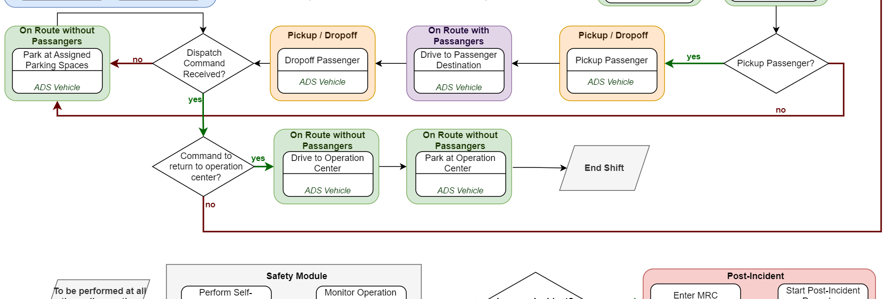
The roles and responsibilities of the ADS vehicle, FOC, and MOC staff may change during different operational phases. An example operational scheme is shown in Figure 3. The stages considered are:
- Inspection and maintenance: The vehicle must be inspected and approved before each shift.
- On-route to destination with & without passenger: The vehicle performs DDTs and context-aware fallbacks.
- Passenger pick-up and drop-off: The rider coordinates the trip information through the mobile app for pick-up and after drop-off.
- Post-incident management: The remote operator coordinates incident response after the vehicle MRC is triggered by self-diagnostic module or passenger request.
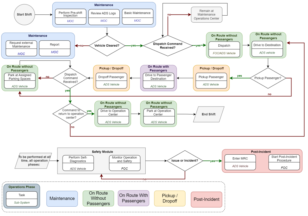
Figure 3: Simplified diagram of operational phases.
2. Scenario Modeling: Process Overview
We use the methodology in Figure 1 to describe each of the operational phases – aiming to identify critical functions and interactions contributing to hazard scenario development.
The tasks of the ADS vehicle, the remote operators at the FOC, and the crew stationed at the MOC have been divided based on the IDA cognitive model (Information, Decision, Action) (Chang & Mosleh, 2007). This task decomposition approach aids the identification of hazards separating the communication agents (incomplete, imperfect, or faulty information), channels (hardware, software, or connectivity issues) and receptors (failure to identify and process information) prior to the decision-making process.
A summary of all the models created to represent this generic fleet is shown in Figure 4:
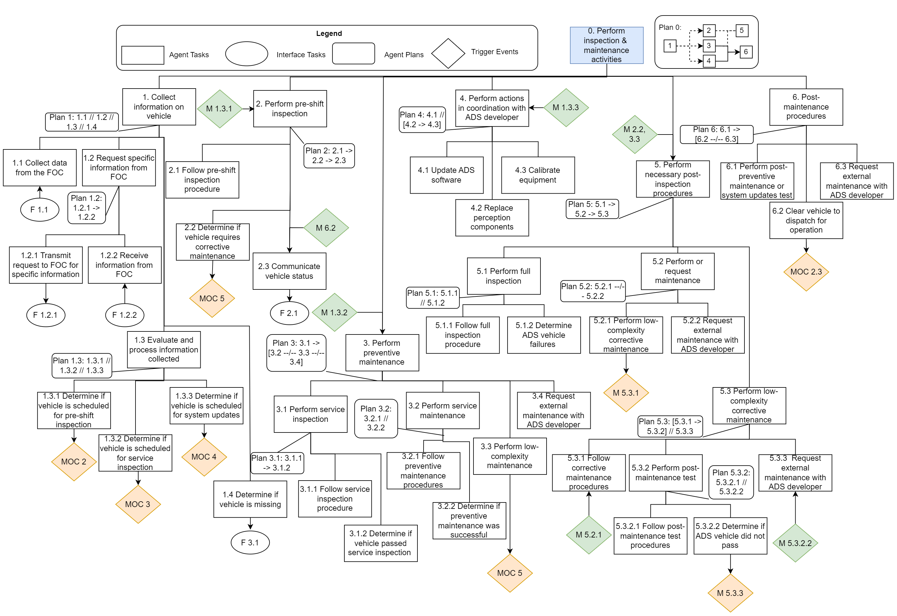
- Event Sequence Diagrams: An ESD for each operational phase, from a defined initiating event to end-states with varying levels of severity. Each ESD event is associated with one of the three agents: the ADS vehicle, FOC operators, or MOC crew.
- Concurrent Task Analysis: A CoTA represents the tasks required for an ESD event success. A CoTA diagram is created for each agent involved in each operational phase, detailing the hierarchy and dependency of subsystem functions and interactions.
- Fault Trees: Complementary FT model the failure of some pivotal ESD events to determine and categorize the nature of the basic failures (i.e., human error, software or hardware malfunction, design error).
- System-Theoretic Process Analysis: A system-level STPA is developed to identify critical communication channels and feedback loops, describing subsystem functions and interactions.
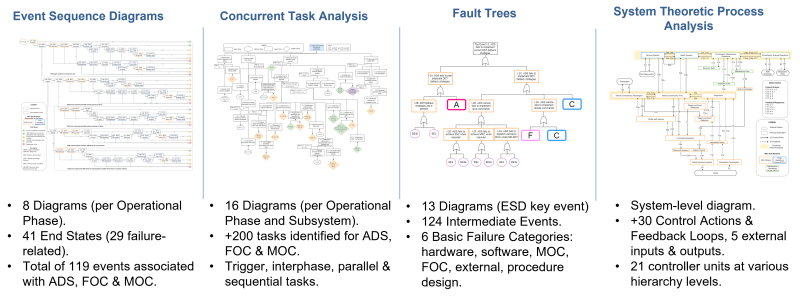
Figure 4: Summary of developed models.
Click here to learn more about Concurrent Task Analysis and System-Theoretic Process Analysis applications analyzing inspection and maintenance activities in fleet operations.
Please reach out to the project PI for access to the project’s full documentation.
3. Hazard Identification
The hazard identification process leverages the modeling tools to categorize and compare identified hazards (Figure 5). The results are consolidated into a Hazard Catalog, where each failure mode is associated with a single Risk Contributor (Table 1) and each hazard can potentially lead to various consequences, assessed through a Qualitative Risk Scale.
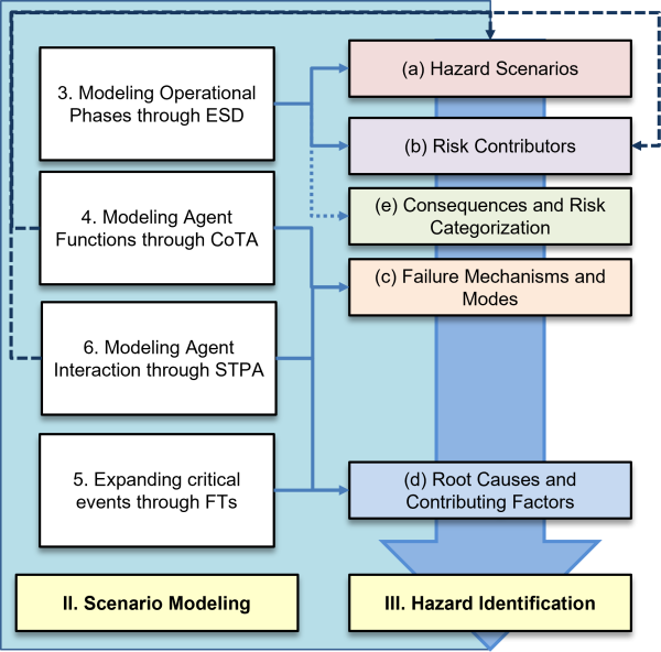
Figure 5: Hazard modeling and identification framework.
- The safety hazards are based on the failure path of each ESDs event. This process allows the identification of (a) specific hazard scenarios and (b) risk contributors.
- The failure modes and mechanisms involved in the hazard scenario (c) are modeled through the CoTA and STPA. Unsafe interactions are determined by finding the explicit dependency between tasks (CoTA) and errors in controlled feedback loops (STPA).
- FTs are connected to the ESDs through specific top events and characterize of the failure mechanisms developed through the STPA. This process allows identifying and categorizing basic failure events by their possible (d) root causes.
- Consequences are represented by the ESD end-state and are assessed through a qualitative risk scale (e).
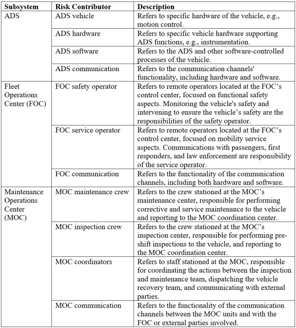
Table 1: Risk contributor breakdown and description.
Qualitative Risk Scale
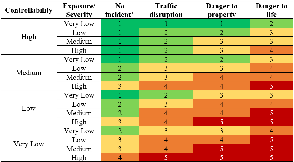
To qualitatively address the risk of each end state, we propose a multi-dimensional qualitative risk scale composed of a combination of “relative frequency”, “controllability” and “severity” inspired by the ISO 26262 ASIL risk assessment methodology. The risk level is categorized on a scale 1-5 shown in Table 2.
- Level 1: Operation proceeds as expected or operational failures do not lead to imminent risks.
- Level 2: Low-level risks. Scenarios where the vehicle operation is interrupted but preventive and mitigative actions are available; or when failures of preventive or mitigate actions do not lead to immediate consequences.
- Level 3: Medium-level risk. Scenarios in which the vehicle’s operation is interrupted and mitigative actions are available; or when failures of mitigative actions do not lead to immediate consequences.
- Level 4: High risk. Scenarios where an incident has occurred, or the vehicle’s operation is interrupted. Mitigative actions have failed or have not been performed, leading to immediate consequences.
- Level 5: Very high risk. Scenarios where the vehicle is at risk of collision, involves passengers or other road users, and mitigative actions have failed or have not been performed and lead to immediate consequences.
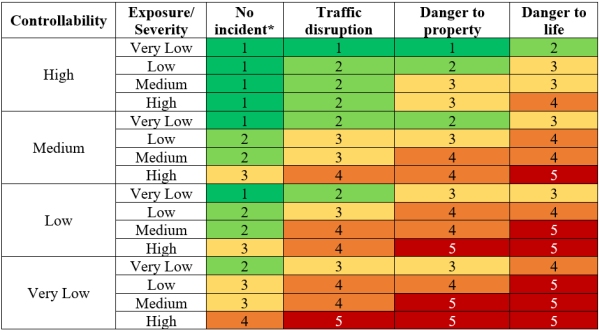
Table 2: Qualitative risk matrix.
*Severity Level 1: No incidents correspond to scenarios in which operation does not lead to any traffic, property, or injury related consequence, e.g., a passenger trip has successfully been completed. However, organizational errors and failure to follow procedures are also considered at this level as these do not produce any immediate consequences, e.g., the ADS vehicle has been incorrectly cleared for operation after failing a pre-shift inspection test.
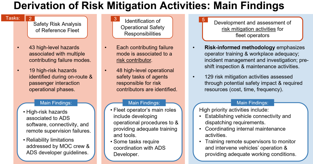
Main Findings
The hazard identification process revealed 43 safety hazard scenarios involving 912 failure modes across the functions of ADS vehicles, FOC remote operators, and MOC crew. The key findings are:
- Operational Design Domain (ODD) Restrictions: Fleet operators might need to restrict the ODD more than the ADS developers’ design to ensure reliable communication with passengers and the FOC. This more restrictive ODD highlights the need for stringent cybersecurity and wireless communication stability.
- Human-System Interaction (HSI) Tools: The system design and HSI tools must account for human and physical time constraints, giving remote operators at the FOC adequate time for monitoring and driving assistance tasks (Mutzenich et al., 2021).
- Maintenance Crew Training: Proper training and maintenance procedures are vital in preventing hardware and software failures. Depending on the information asymmetry between ADS developers and fleet operators, different reporting and oversight policies might be required. Alternatively, ADS developers could provide a comprehensive service package, including all inspection and maintenance operations.
Please reach out to the project PI for access to the full Hazard Catalog.
Addressing Safety Hazards: Deriving Risk Mitigation Activities
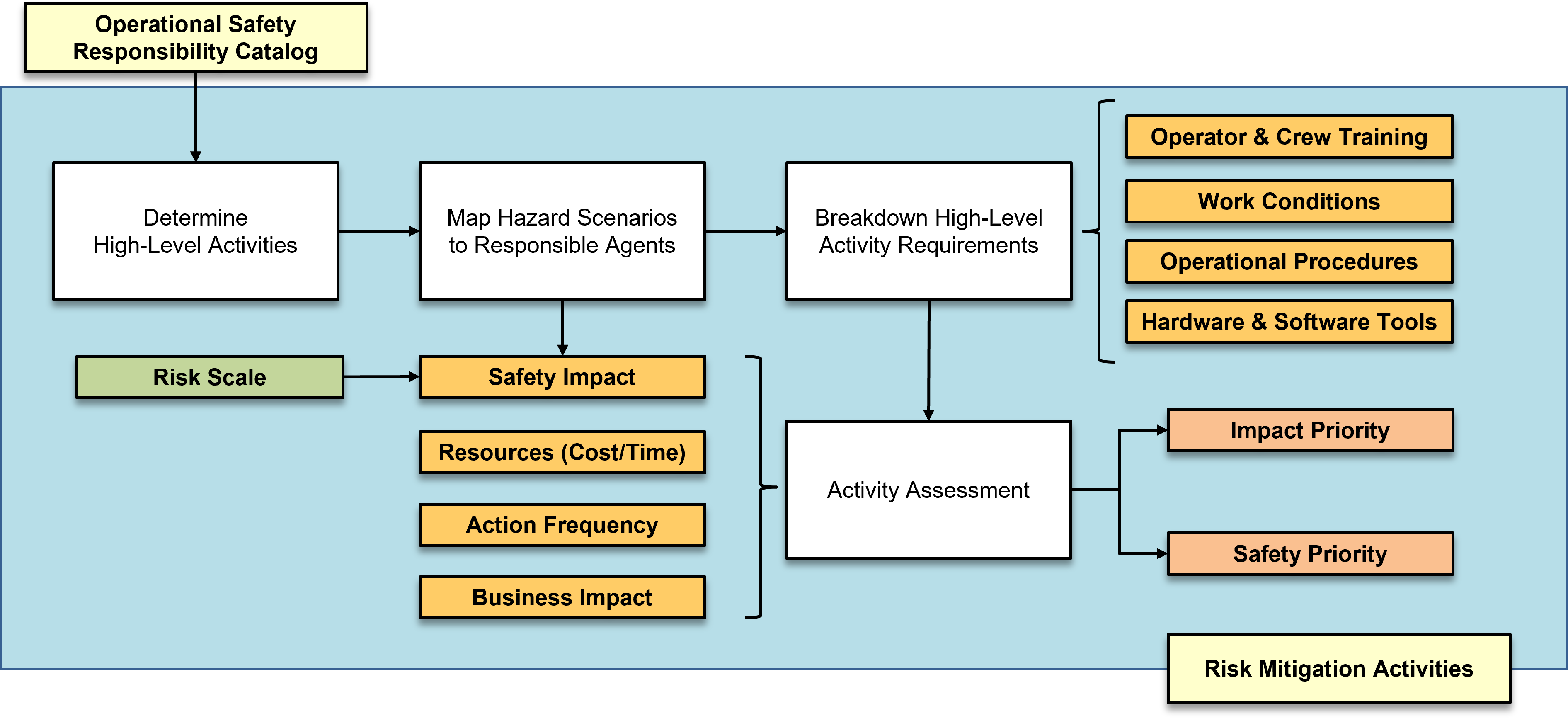
Identification of Operational Safety Responsibilities
After identifying the main safety hazards, the next stage is to determine what are the operational safety responsibilities involved in (a) preventing or (b) mitigating the hazards that arise from malfunctions, errors, or failures of the system’s risk contributors.
Each operational safety responsibility is supported by a higher-level activity performed by the Fleet Operator: complying with operational requirements, implementing operational procedures, and supporting each agent to perform their tasks. These high-level activity requirements mapping process is shown in Figure 6.
The identified safety responsibilities are complemented by those through the review of industry best practices in:
- Other transportation types such as light vehicles and heavy trucks for passenger and commercial transport.
- Industries with control room environments and varying levels of automation such as nuclear, civil and commercial aviation, autonomous marine vessels, and railway systems.
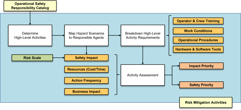
Figure 6: Derivation and Assessment of Risk Mitigation Activities.
Developing Recommendations
The risk mitigation activities are derived by investigating what elements are required from the Fleet Operator to provide the adequate support to the system’s agents in carrying out their operational safety responsibilities. In general, this consists of a detailed list of what kind of procedures, training, tools, and working conditions may be beneficial to preventing and mitigating operational risks:
- Operational Procedures: Operational guidelines to support the activities of the human operators and the operating conditions of the ADS vehicle. These refer to both emergency operating procedures and standard operating procedures. These procedures include the content, frequency, and requirements for communications, activities, and interactions between the agents and external entities.
- Operator & Crew Training: Training provided to the FOC operators and MOC crew. The training content includes familiarization with the operational procedures, required Human-System Interface (HSI) functions, emergency procedures, and workplace safety guidelines.
- Hardware & Software Tools: Hardware and software tools necessary for the agents to perform expected tasks. These include required communication devices, reliable connectivity conditions, passenger interaction devices, and tools to support maintenance activities.
- Work Conditions: General policies and equipment designed to improve multiple aspects of workplace adequacy for expected crew performance.
The analysis resulted in 140 risk mitigation activities, each assessed through the potential safety impact and required implementation resources (cost, time, frequency). This list contains activities that impact the tasks and performance of multiple target agents, spanning operator and crew training, operational procedure development, software and hardware tools, and workplace adequacy factors.
Activity Impact Assessment
Each risk mitigation activity is assigned a business impact category based on the potential safety impact, the estimated resources (cost, time) required for implementation, and how frequently the Fleet Operator should implement them.
- Safety Impact: The safety impact is represented by a relative risk level, calculated as a combination of the risk level of the hazards prevented or mitigated by these activities and the relative importance of the activity for each target agent.
- Resources (Cost, Time, & Frequency): This is a qualitative measure of the cost and time required to implement the activities, as well as how frequently these are needed to be performed or updated.
- Business Priority Rank: Each risk mitigation activity is characterized by the three category-based scales (cost, time, frequency) and the safety impact (derived from the risk scale). A combination of these scales is consolidated into a business impact four-dimensional matrix.
- Safety Priority Rank: Some activities with high safety impact may require a higher implementation cost or time or need to be implemented periodically or constantly. This business impact scale would then rank these activities with a low priority. Hence, any risk mitigation activity with a “Very High” or “High” safety impact is prioritized, overriding the business impact scale for those activities.
Please reach out to the project PI for access to the project’s full documentation.